Home |
Clinamen | Philosophy | Customer reviews | White paper | Pricing policy | Contact


cartridge/ step up transformer matching
The step-up transformer, if used as a passive gain unit for moving coil cartridges supplies two very important functions:
- It elevates the output tension of the cartridge of a value between 20 and 30 dBs, depending on the turns ratio ( n) of the transformer.
- It works as an impedance adapter, showing the cartridge the right load impedance. It is well known that a Moving Coil cartridge must work with a load around 10 times its internal impedance. Thus the transformer must allow for the impedance on the secondary (which is the input pre-phono impedance), once reflected on the primary, to be around 10 times the internal resistance of the cartridge. The calculation is quite simple. The Z reflected on the primary is obtained by dividing the Z on the secondary by the square of the turns ratio ( n) . In order for the cartridge to see the right load we can only act on the turn ratio and on the input pre-phono impedance. In the image we can see an example of a Denon Dl103 with a 1:10 step up; it is much clearer than words.
Calculation of the pre-phono reflected impedance
Image content:
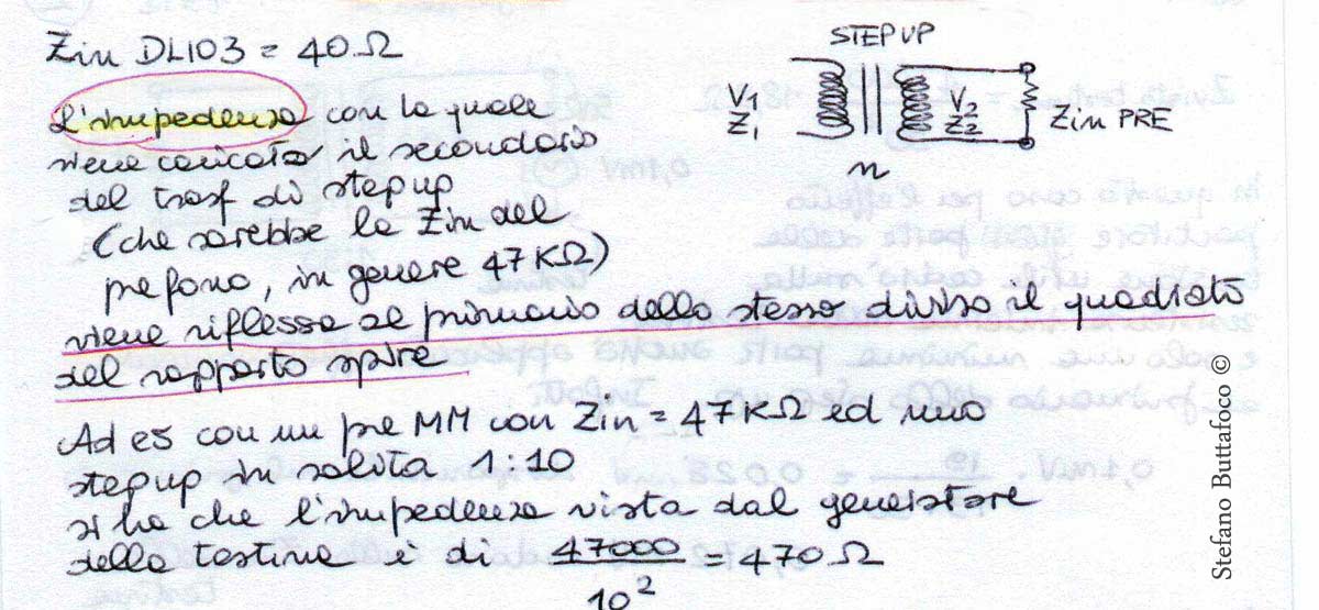
" Zin DL103 = 40 Ω
The impedance with which the secondary of the step-up transformer is loaded (it is the pre-phono Zin, usually 47kΩ) is reflected on the primary of the same divided by the square of the transformation ratio.
For example with an MM preamp with Zin=47kΩ and a step-up with n = 1:10 , we have that the impedance seen by the generator of the cartridge is 47,000/102 = 470Ω "
The tension that the cartridge will manage to transfer on the secondary of the transformer depends on the spire ratio, but this is a theoretical maximum value. In practice the phenomenon of the divider effect will make available a smaller percentage of this theoretical value on the secondary.
In the quantification of the divider effect two variables play a role: the internal impedance of the cartridge and the transformation ratio of the step-up. You see that the understanding of this phenomenon will lead us to state that high internal impedance cartridges must not be matched with very high turns ratio step-up transformers.
The divider effect represents the fall of tension on the internal impedance of the cartridge, a signal which will not be applied to the transformer. It is the mechanical equivalent of attrite and it is good practice to minimize it in order to have the highest transfer of usable signal.
The divider effect is higher the more the internal impedance of the cartridge is comparable to the reflected impedance of the pre-phono on the primary.
A high turns ratio step-up reflects very low impedance on the primary because the square of the spire ratio is very high. This is the reason why the internal resistance of the cartridge must be very low to be matched with a high increase step-up, otherwise most of the tension generated by the cartridge won’t actually be made available and the cartridge generator will work in a condition of overload (not as a tension generator any longer).
Let’s see two examples that help us verify the divider effect generated by two different transformers on the same cartridge.
Divider effect with step-up 1:10 and cartridge with Zin 50 ohm
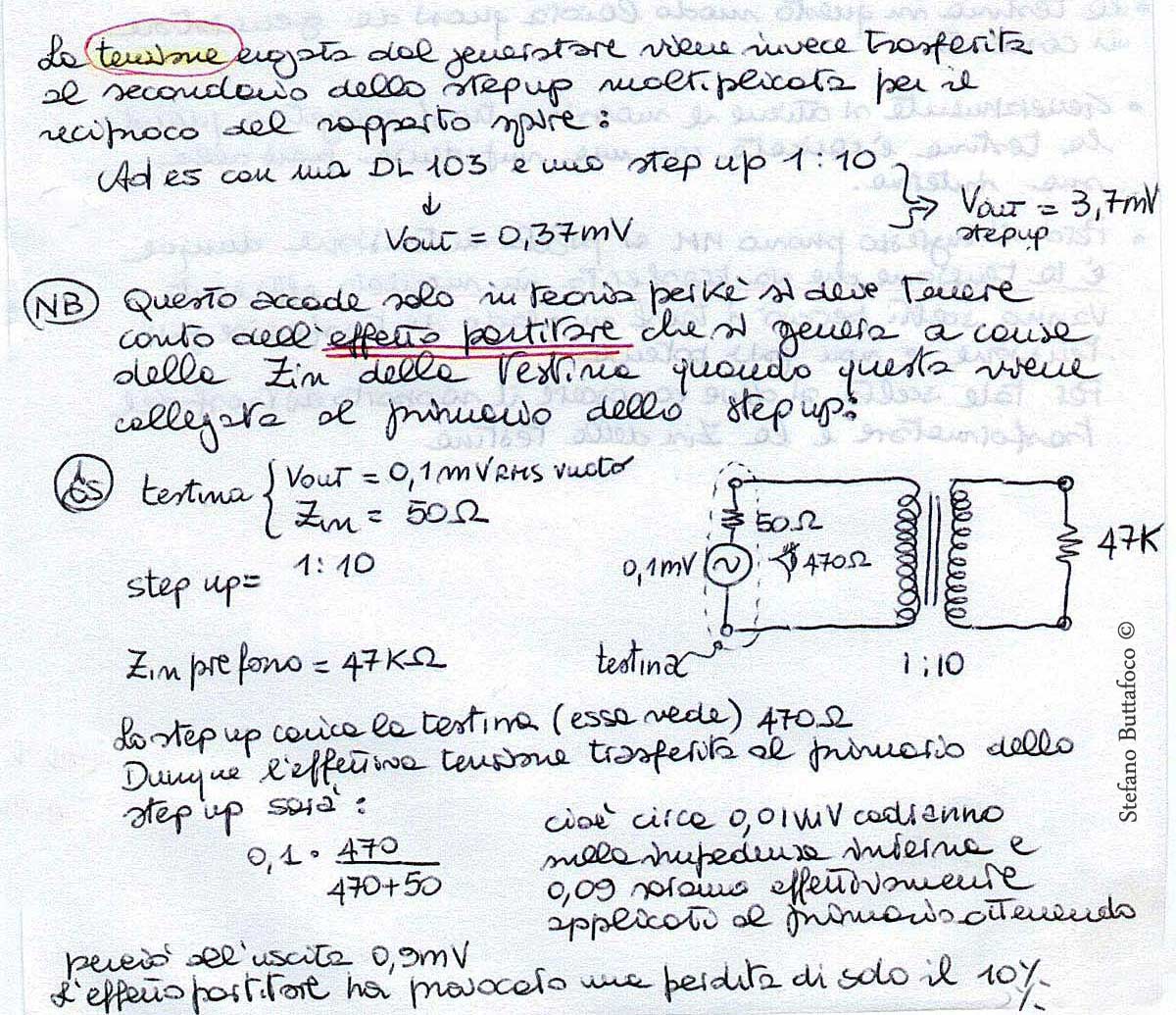
Image content
The tension supplied by the generator is transferred on to the secondary of the step-up multiplied by the reciprocal of the spire ratio:
For example with a DL103 (cartridge output voltage= 0.37mV) and a step-up 1:10 =>Voltage output from step up=3.7mV
NB. This occurs only in theory, because we need to consider the divider effect that is generated due to the Zin of the cartridge when the latter is connected to the step-up primary.
Cartridge Data: output voltage= 0.1 mV RMS without load, Zin = 50 Ω
Step-up = 1:10
Pre-phono Zin = 47 KΩ
The step-up loads the cartridge (it sees) with a resistive value of 470Ω
Thus the actual tension transferred to the step-up primary is:
0.1 x 470/470+50 that is circa 0.01 μV will fall on the input impedance and 0.09 will actually be applied to the primary, resulting in 0.9 mV at the secondary coil of the trnasformer (output)
The divider effect only caused a 10% loss.
Divider effect with step-up 1:50 and cartridge with Zin 50 ohm
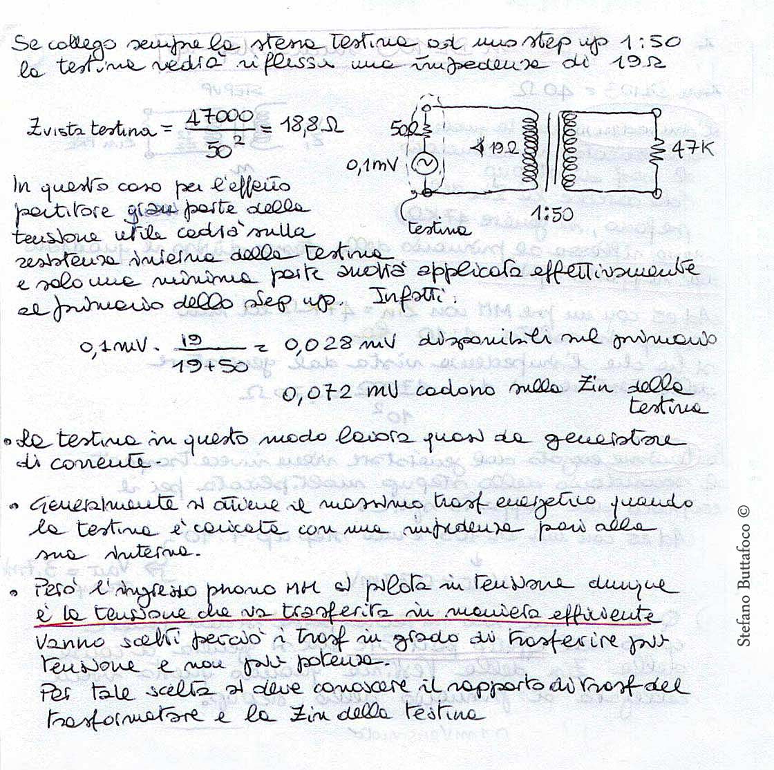
Image content
If I connect the same cartridge ( Zin 50 ohm and Voltage output 0,1 mV) to a step-up 1:50 the cartridge will see 19 Ω impedance reflected.
Z ‘seen’ by the cartridge = 47000/502 = 18,8Ω
In this instance due to the divider effect most of the usable tension will fall on the internal resistance of the cartridge and only a small part will be actually applied to the step-up primary. Indeed:
0,1 mV x 19/18+50 = 0.028m/v available on the primary
0,072 mV fall on the cartridge Zin
- The cartridge in this instance works almost as a power supply
- We usually get the maximum energy transfer when the cartridge is loaded with impedance equal to its internal impedance.
- But the MM phono input is piloted in tension, therefore tension must be transferred efficiently. Thus we need to choose transformers able to transfer more tension rather than more power.
- In order to make this choice we need to know the transformation ratio of the transformer and the cartridge’s Zin.
.....RECAPITULATE.......
Therefore cartridges with an internal impedance of tens of Ohms MUST NOT be interfaced with high turns ratio step-ups. On the other hand cartridges with high internal impedance (and by high I mean values between 20 and 50 Ohms) hardly need high levels of step-up, since their output level is usually quite high.
Cartridges with low internal impedance value can work with high turns ratio step-up (from 1:20 to 1:30), because the internal resistance will still be much lower than the impedance reflected on the primary. Furthermore the high level of step-up is necessary to elevate the usually low tension that these cartridges are able to supply.
Clinamenaudio • Ing. Stefano Buttafoco
Contrada Barattelli 3A
San Benedetto del Tronto (AP) 63074
C.F.: BTTSFN74M01H769L / P.IVA: 02123590446
Registro AEE : IT20070000012328
Tel. cellulare (+39) 340 8756612
Tel. laboratorio (+39) 0735 782043
E-mail: info@clinamenaudio.com
Instagram ![]() :https://instagram.com/clinamenaudio
:https://instagram.com/clinamenaudio